What Understanding Current Limiting Circuits: The Safety Guardians
Current-limiting circuits are vital in modern electronics, acting as critical safety components to prevent overheating and component failures. As outlined by safety standards like NEC/NFPA 70, these circuits significantly reduce fault currents, serving as a 'safety valve' for electronic systems. This guide explores their functionality, diverse types, and essential applications.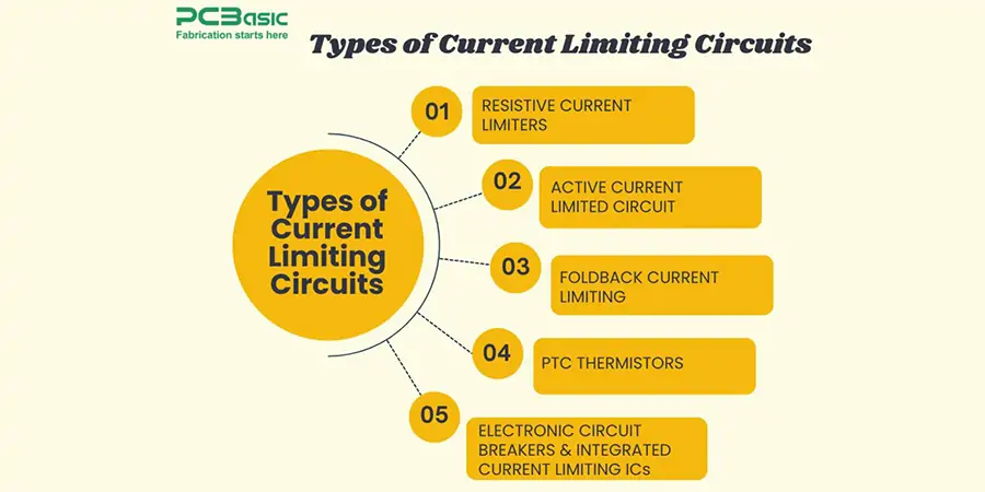
We'll delve into the two primary approaches: constant current limiting and fold-back current limiting. Each offers unique protective advantages, with fold-back designs often demonstrating superior efficiency. From safeguarding sensitive data components to securing industrial power supplies, this guide illuminates the broad applicability and importance of these circuits.
Types Different of Current Limiting Circuits
Current limiting circuits come in various forms, each tailored to specific applications and safety requirements. Understanding the nuances between these types is crucial for selecting the right safety mechanism for your circuits.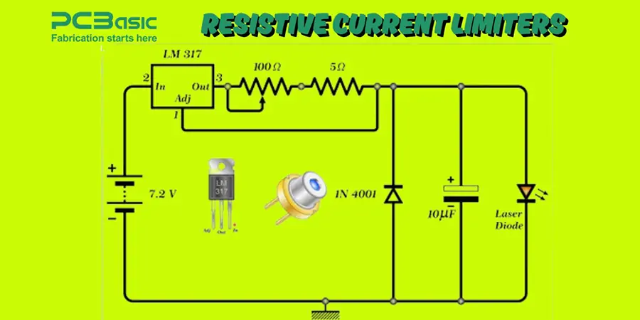
Resistive current limiters are the simplest form, using a resistor to limit current. They are based on Ohm's law, with a voltage drop proportional to the current. However, they dissipate power constantly, making them less efficient than active alternatives.
Active current limiting circuits utilize transistors or specialized ICs as control elements. The basic transistor setup includes a sensing resistor that triggers the transistor when the current exceeds a threshold. Sophisticated designs often incorporate operational amplifiers for precise power control and threshold adjustments.
Foldback current limiting offers an elegant solution, reducing output current as the fault severity increases. This approach reduces power waste during short circuits and protects the load from damage. It is significantly more efficient than constant current limiting, especially during fault conditions.
PTC (Positive Temperature Coefficient) thermistors provide self-resetting protection. These components dramatically increase resistance when overheated, effectively limiting the circuit. Once the fault is resolved and the thermistor cools, normal operation resumes without manual intervention.
Electronic circuit breakers combine solid-state switches with advanced detection circuits. These react faster than mechanical switches, ideal for sensitive electronics. Integrated current-limiting ICs offer complete solutions, including adjustable thresholds, fault indications, and automatic recovery, and modern designs often include thermal shutdown and under-voltage lockouts, among other safety features.
How Current Limiting Circuits Work: Detection and Intervention
The fundamental principle behind current-limiting circuits is detection and intervention. These circuits constantly monitor current flow, reacting when it exceeds a predefined threshold. Unlike simple conductors, current-limiting systems introduce controlled impedance to maintain safe operation.
At its core, a current-limiting circuit uses a sensing component to detect excessive current. This sensing element measures the current flow.
Upon detecting overcurrent, the circuit responds by increasing resistance or reducing voltage. This often involves a transistor switching from linear to saturation mode, which effectively provides impedance to the circuit.
A 'brick wall' power limit maintains the output voltage up to a set limit and then holds the current stable, proportionally dropping the voltage to the load. This sudden limiting action defines its name.
For more advanced safety, fold-back circuits reduce current as the fault worsens, significantly minimizing power waste during failures. This method can reduce the wasted current dramatically compared to constant power designs.
“Current limiting circuits are the unsung heroes of electronic safety, protecting components and systems from catastrophic failures.
Electronics Engineer
Explore Current Limiting
Interactive elements to deepen your understanding
Interactive Circuit Diagrams
Explore various current limiting circuit designs with interactive diagrams. See how each component contributes to the overall safety mechanism.
Current Limiting Simulation
Simulate the effects of different current limiting approaches under various fault conditions. Experiment with settings and observe the results.
Pros & Cons Advantages and Disadvantages of Current Limiting Circuits
Current limiting circuits offer significant benefits but also present certain drawbacks. Understanding these trade-offs is essential for informed design decisions.
Advantages: Component protection, enhanced safety, thermal benefits, reduced electrodynamic forces, improved system reliability, error current reduction, EMI control, and cost savings.
Component Protection: Prevents damage to sensitive components, ensuring longevity.
Enhanced Safety: Protects essential electrical components, like cables and switches, reducing overheating and fire hazards.
Thermal Benefits: Maintains lower operating temperatures, increasing component lifespan.
Reduced Electrodynamic Forces: Minimizes mechanical deformation in connectors and rails, improving durability.
Improved System Reliability: Ensures stable electrical operation, reducing unexpected errors.
Error Current Reduction: Controls fault currents, preventing short circuits and component damage.
EMI Control: Reduces electromagnetic interference, crucial for sensitive devices.
Cost Savings: Enables the use of smaller, more affordable components.
Disadvantages: Increased complexity and cost, high set points and tolerance, significant heat generation, temperature sensitivity, and challenges with foldback current limiting.